Guide Element Height & Width Calculations
- Home
- Guide Elements
- Guide Element Height & Width Calculations
The elastic deformation of the components under the load (deflection of the guide element, bending of the shaft, extending/shrinking of the cylinder) creates an angular deviation between the piston and bore or rod and gland cap. Calculation based on the parallel axis generally gives wrong conclusions.
In this respect it is vital to take this into consideration when calculating the guide elements.
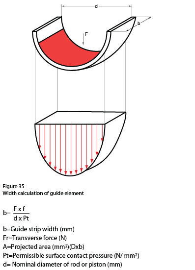
Geometric consideration (angular deviation, additional force applications to the system, etc) should be taken into account when calculating the transverse load applied on the guide element and also the elastic deformation of all components involved (deflection of the guide element, bending of the shaft, stretching of the cylinder, etc). In this respect while making
the calculations a safety factor (generally around 2) should be identified.
In long slender cylinders the permissible transverse force is limited by the bending strength of the rod and other factors. The general assumption that about 10% to 15% of the hydraulic force is applied as a transverse load.

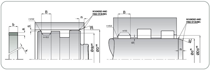
It is not required to have metal to metal contact with piston-bore and rod-gland cap. That is why under the transverse forces, maximum angular deviation for the guide element should be less than the permissible sealing gap defined in the catalogue.
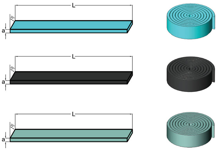
GUIDE LENGTH CALCULATIONS IN GUIDE STRIP
L = Guide strip length (mm) D = Nominal diameter of piston (mm)
d = Nominal diameter of rod (mm) a = Cross-sectional thickness of the guide strip (mm)


